Cross sections produced by Civil 3D can be automatically put into custom sheets, paperspace layouts and sheet sets.
How to do it...
First of all create a new dwt.
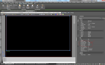
Then create a new paperspace layout using a name which points to the plotter, sheet size and orientation, and the scale to be used so that it is recognisable.
Modify it to the desired plotter type, sheet size and orientation and scale.
Scale is crucial.
At the viewport frame properties Annotation and Standard Scales should be identical.
The above steps can be followed for creating various combinations.

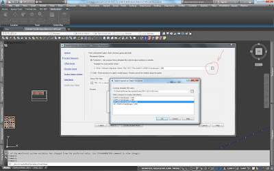
In dwg file Create multiple section views, select Section placement, press the button next to Production, select the desired dwt and finally select the desired paperspace layout to use.
It is crucial for all scales to be identical.
Layout selected Annotation and Standard scales should be the same with current dwg scale.

After selecting all the other desired settings then sheets are automatically created.
Those sheet objects now only exist in model space. In order to automatically create paperspace layouts...
either type CREATESECTIONSHEETS at the command line
...or click on a sheet object which results into displaying the Section sheet panel from which press the button Create section sheets
and now be careful to make all the proper and desired selections
Now paperspace layouts are created, also sheet set that point to those paperspace layouts.
Critical tips :
When creating dwt beware of layer property "New VP freeze". If set to freeze for a layer that is supposed to be Visible (thawed) then objects set in this layer will be invisible.Beware also of the same property for layers in dwg.
Section views group original insertion position is for life. Once created then the whole pack cannot be permantly moved. Once Update layout takes place then everything goes back. It is also a bad practice to move them since PaperSpace Layout ViewPorts will point to original position. It can be moved to target the expected window but it is meaningless.
Further Tips :
Neither Sheet objects nor Layout objects are updated in case dwt paperspace layouts change. Recreation of section sheets and PaperSpace layouts must take place.
It does not work like XREFs or DataShortcuts. Unfortunately!
Beware of the scales. All of them must be equal
Or have a proper custom scale (Standard to annotation ratio) ! In such a case
Sheet objects can not be further proccessed once created. No properties. No nothing!
Just click on it to display Ribbon tab Section sheet and get the option to create Paperspace layouts and SheetSets. That's all.
Clicking on it and then right click displays a dropdown menu with no further usefull options.
I guess this is an area that autodesk has lots of options for future additions.
Watch out about manually erasing Section View Objects!
If all section view objects within a Section View Group are erased then the Section View Group object is not erased! It still exists but it does not react to right click Properties or Update layout.
Sheet objects do also exist. They must be manually erased but even though, Section View Group is not erased!
In case a Section View Group is deleted then all remaining empty sheets are deleted.
If some section view objects are manually erased then doing Update Layout on anyone of the remaing ones, erases empty sheets.
In whatever every deletion case all PaperSpace layouts still exist but Section View objects erased are missing from within Viewports. They must be manually erased.
Sheet sets are also not affected in whatever above deletion case. They still point to those deleted or affected dwg PaperSpace layouts. When selecting then a message appears prompting to either erase the link or set it to another PS layout.


