Thursday, 16 March 2017

Civil 3D 2017 custom programme, Section views Elevation Minimum set on the fly

Elevation minimum of selected section views can be changed on the fly with this custom programme-plug in, for Civil 3D 2017.

First download the plug in...
https://www.dropbox.com/s/bhpgymcp4herkdq/C3D2017_SectionViewElevMin.dll?dl=0
and save it anywhere you want

Then when in autocad at command line enter NETLOAD and select C3D2017_SectionViewElevMin.dll

At the command line enter setHRZ
enter the new horizon (minimum elevation)
select the desired section views

Finally right click on a section view line and select Update Section View Layout


AutoCAD object properties exposed by Active X as ReadOnly

Visual LISP is great tool considering portability and debugging.
It uses active x to get objects.
There are properties exposed by active x that are exposed as Read Only while in NET they are exposed as Read Write !
For example in Civil 3D, section views, elevation min/max, offset left/right are ReadOnly when getting through active x. So i had to turn to NET to change their values.

So a good practice before starting developing using VBA or Visual Lisp is to check whether properties are exposed by active x and if so if they are writeable.

A on the fly method to get the available properties and their RW availability is through command line entering the following command.

(vlax-dump-object (vlax-ename->vla-object (car (entsel))) T)

The T at the end asks for the available methods and can be omitted.
The (RO) next to property indicates that are Read Only.

Following is a copy-paste from the results in command window (F2)...

; IAeccSectionView: interface IAeccSectionView
; Property values:
;   Application (RO) = #<VLA-OBJECT IAeccApplication 000000007499ce10>
;   BandSet (RO) = #<VLA-OBJECT IAeccSectionViewBandSet 000000007499e5b8>
;   Description = ""
;   DisplayName (RO) = "0+880 (45)"
;   Document (RO) = #<VLA-OBJECT IAeccDocument 0000000074996570>
;   ElevationMax (RO) = 35.0
;   ElevationMin (RO) = 28.0
;   EntityTransparency = "ByLayer"
;   Handle (RO) = "8C4D"
;   HasExtensionDictionary (RO) = 0
;   Hyperlinks (RO) = #<VLA-OBJECT IAcadHyperlinks 0000000075afed68>
;   Layer = "Sections & Section Views Dev"
;   LengthLeft (RO) = -11.2552
;   LengthRight (RO) = 31.6704
;   Linetype = "ByLayer"
;   LinetypeScale = 1.0
;   Lineweight = -1
;   Material = "ByLayer"
;   Name = "0+880 (45)"
;   ObjectID (RO) = 42
;   ObjectName (RO) = "AeccDbGraphCrossSection"
;   OffsetLeft (RO) = -11.2552
;   OffsetRight (RO) = 31.6704
;   Overrides (RO) = #<VLA-OBJECT IAeccSectionOverrides 000000007499aec8>
;   OwnerID (RO) = 43
;   Parent (RO) = #<VLA-OBJECT IAeccSampleLine 000000004bd402b0>
;   PlotStyleName = "ByLayer"
;   ShowToolTip = -1
;   Style = #<VLA-OBJECT IAeccSectionViewStyle 000000004fc38ed0>
;   StyleName (RO) = "TKV - CS name and station"
;   TrueColor = #<VLA-OBJECT IAcadAcCmColor 0000000075afea00>
;   Type (RO) = 4
;   VerticalScale = 1.0
;   Visible = -1
; Methods supported:
;   ArrayPolar (3)
;   ArrayRectangular (6)
;   Copy ()
;   Delete ()
;   FindStationOffsetAndElevationAtXY (6)
;   FindXYAtStationOffsetAndElevation (6)
;   GetBoundingBox (2)
;   GetExtensionDictionary ()
;   GetXData (3)
;   Highlight (1)
;   IntersectWith (2)
;   IsReferenceObject ()
;   IsReferenceStale ()
;   IsReferenceSubObject ()
;   IsReferenceValid ()
;   IsValid ()
;   Layout ()
;   Mirror (2)
;   Mirror3D (3)
;   Move (2)
;   Rotate (2)
;   Rotate3D (3)
;   ScaleEntity (2)
;   SetXData (2)
;   TransformBy (1)
;   Update ()
T

Wednesday, 11 January 2017

Link updates

Today, Wednesday 11 January 2017, i updated all the previously mentioned links since DropBox changed its policy about Public folders.

Funny thing. I saw some sites that accessed my blog. I entered them. All of them were for...adults! Obviously only internet bots visit this blog!

So i keep going on with my main purpose which is to have an online from anywhere accessible site from which i can review my past tips, tricks, workarounds etc.

Civil 3D cross sections to sheets/layouts/sheetsets

Cross sections produced by Civil 3D can be automatically put into custom sheets, paperspace layouts and sheet sets.

How to do it...

First of all create a new dwt.
Then create a new paperspace layout using a name which points to the plotter, sheet size and orientation, and the scale to be used so that it is recognisable.
Modify it to the desired plotter type, sheet size and orientation and scale.
Scale is crucial. At the viewport frame properties Annotation and Standard Scales should be identical.

The above steps can be followed for creating various combinations.
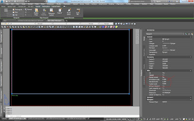


In dwg file Create multiple section views, select Section placement, press the button next to Production, select the desired dwt and finally select the desired paperspace layout to use.
It is crucial for all scales to be identical.
Layout selected Annotation and Standard scales should be the same with current dwg scale.
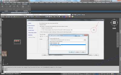


After selecting all the other desired settings then sheets are automatically created.


Those sheet objects now only exist in model space. In order to automatically create paperspace layouts...
either type CREATESECTIONSHEETS at the command line
...or  click on a sheet object which results into displaying the Section sheet panel from which press the button Create section sheets
and now be careful to make all the proper and desired selections


Now paperspace layouts are created, also sheet set that point to those paperspace layouts.

Critical tips :


When creating dwt beware of layer property "New VP freeze". If set to freeze for a layer that is supposed to be Visible (thawed) then objects set in this layer will be invisible.
Beware also of the same property for layers in dwg.


Section views group original insertion position is for life. Once created then the whole pack cannot be permantly moved. Once Update layout takes place then everything goes back. It is also a bad practice to move them since PaperSpace Layout ViewPorts will point to original position. It can be moved to target the expected window but it is meaningless.


Further Tips :

Neither Sheet objects nor Layout objects are updated in case dwt paperspace layouts change. Recreation of section sheets and PaperSpace layouts must take place.
It does not work like XREFs or DataShortcuts. Unfortunately!

 
Beware of the scales. All of them must be equal
Or have a proper custom scale (Standard to annotation ratio) ! In such a case

Sheet objects can not be further proccessed once created. No properties. No nothing!
Just click on it to display Ribbon tab Section sheet and get the option to create Paperspace layouts and SheetSets. That's all.
Clicking on it and then right click displays a dropdown menu with no further usefull options.
I guess this is an area that autodesk has lots of options for future additions.


Watch out about manually erasing Section View Objects!

If all section view objects within a Section View Group are erased then the Section View Group object is not erased! It still exists but it does not react to right click Properties or Update layout.
Sheet objects do also exist. They must be manually erased but even though, Section View Group is not erased!
In case a Section View Group is deleted then all remaining empty sheets are deleted.

If some section view objects are manually erased then doing Update Layout on anyone of the remaing ones, erases empty sheets.

In whatever every deletion case all PaperSpace layouts still exist but Section View objects erased are missing from within Viewports. They must be manually erased.
Sheet sets are also not affected in whatever above deletion case. They still point to those deleted or affected dwg PaperSpace layouts. When selecting then a message appears prompting to either erase the link or set it to another PS layout.


Civil 3D 2017 paths...

Custom subassemblies using NET
"C:\Program Files\Autodesk\AutoCAD 2017\C3D\Sample\Civil 3D API\C3DStockSubassemblies"

Project reference path for COM programming
"C:\Program Files\Common Files\Autodesk Shared\Civil Engineering 110"

Basic project reference files for autocad NET programming
acdbmgd.dll, acmgd.dll, AecBaseMgd.dll, AeccDbMgd.dll, accoremgd.dll
also files
Autodesk.AutoCAD.Interop, Autodesk.AutoCAD.Interop.Common
all of them found at
"C:\Program Files\Autodesk\AutoCAD 2017"

Basic project reference files for Civil 3D NET programming
Autodesk.AEC.Interop.Base, Autodesk.AEC.Interop.UIBase
found at
"C:\Program Files\Autodesk\AutoCAD 2017\ACA"
also files
Autodesk.AEC.Interop.Land, Autodesk.AEC.Interop.UiLand
Autodesk.AEC.Interop.Roadway, Autodesk.AEC.Interop.UiRoadway
and others
found at
"C:\Program Files\Autodesk\AutoCAD 2017\C3D"

Imported custom subassemblies
"C:\ProgramData\Autodesk\C3D 2017\enu\Imported Tools"

Custom Assemblies dragged to palettes
"C:\ProgramData\Autodesk\C3D 2017\enu\Assemblies"

Original autodesk templates
"C:\Users\LS-W7\AppData\Local\Autodesk\C3D 2017\enu\Template"

Original autodesk ToolPalettes
"C:\Users\LS-W7\AppData\Roaming\Autodesk\C3D 2017\enu\Support\ToolPalette\Palettes"

AeccContent_Dir, C3DStockSubassemblyScripts.codes and custom coding

When developing custom subassemblies for Civil 3D using MS.NET there might be a need for custom coding.
There are three ways to do it.

1. Rely on module "CodesSpecific.vb" provided from autodesk.
Developer may add custom codes. But none of it will be avalaible unless the file named "C3DStockSubassemblyScripts.codes" is informed with latest codes.
This file is in the directory which variable AeccContent_Dir points to.
This variable is readonly and its initial value is set when installing Civil 3D. If user does not change its location proposed by autodesk then it points to...
C:\ProgramData\Autodesk\C3D 2017\enu\C3DStockSubassemblyScripts.codes

2. A variation of the above approach is to alter the path and/or the name of the file it points to.
Path is get from the variable "AeccContent_Dir" and file "C3DStockSubassemblyScripts.codes" is set into the constCodesFile. Even alter the whole apporoach of getting the codes.

3. Totally ignore the autodesk coding approach and set codes directly which i think is the best approach.


Trimble TGO GPS site calibrations tips (2)

Beware of the rotation units GON vs Degrees.

On site calibrations can be saved to TGO Coordinate System Manager as Sites and get used to other jobs.

Adjustments is only for Trimble. A site calibration can be reproduced as Datum with TGO GPS calibration as 7 parameter. Original on site job required.